First published: 2024-01-27
Last updated: 2024-01-30
About the Mesh Shading Series
This post is part 4 of a series about mesh shading. My intent in this series is to introduce the various parts of mesh shading in an easy to understand fashion. Well, as easy as I can make it. My objective isn’t to convince you to use mesh shading. I assume you’re reading this post because you’re already interested in mesh shading. Instead, my objective is to explain the mechanics of how to do mesh shading in Direct3D 12, Metal, and Vulkan as best I can. My hope is that you’re able to use this information in your own graphics projects and experiments.
- Mesh Shading Part 1: Rendering Meshlets
- Mesh Shading Part 2: Amplification
- Mesh Shading Part 3: Instancing
- Mesh Shading Part 4: Culling
- Mesh Shading Part 5: LOD Selection
- Mesh Shading Part 6: LOD Calculation
- Mesh Shading Part 7: Culling + LOD
- Mesh Shading Part 8: Vertex Attributes (TBD)
- Mesh Shading Part 9: Barycentric Interpolation (TBD)
Sample Projects for This Post
114_mesh_shader_culling - Demonstrate how to do meshlet culling during amplification.
The D3D12 version of 114_mesh_shader_culling displays pipeline statistics. The Metal and Vulkan versions do not display pipeline statistics for different reasons. Metal doesn’t have pipeline statistics. Turning on pipeline statistics on the Vulkan version tanks the performance. I haven’t had a chance to investigate why this is and how it affects the various GPUs.
Introduction
We have now arrived at one of the cannonical use cases for mesh shading: meshlet culling. This post will cover some different methods of meshlet culling using a meshlet’s bounding sphere and a perspective camera’s view frustum. The main idea is to help establish a basic understanding of meshlet culling. We won’t discuss cone or primitive culling in this post, maybe they’re something a later post can visit.
We’ll start with computing meshlet bounding sphere, then proceed to discuss the view frustum. Afterwards, we’ll cover the remainder of the C++ and shader code changes to make it all work.
Just a heads up, unlike the other posts, this one will not have a rendered image at the end. Instead, there will be lots of images scattered throughout the post to aid some of the topics’ discussions.
The sample for this post builds up from instancing sample. The horse statues are still layed out in columns and rows with different spacing. The camera is now placed in the middle of all the statues so we can see the affects of the culling. The camera can be rotated left and right by left dragging the mouse.
And lastly, we’re upping the columns and rows to 40 by 40, which means we’re reanding 1600 instances of the horse statue.
Computing The Meshlets Bounding Spheres
A meshlet’s bounding sphere is stored in a 4 component vector, e.g. float4 or vec4. The .xyz portion of the vector stores the sphere’s center. The .w component stores the sphere’s radius.
The sphere’s center is in object space. It will later get transformed into world space for our simple culling process.
Using meshopt_computeMeshletBounds To Compute A Meshlet’s Bounding Sphere
Thanks to meshopt, computing the meshlet bounds only requires one additional function: meshopt_computeMeshletBounds().
// We'll need these from before
std::vector<float3>           vertexPositions; // Vertex positions from mesh
std::vector<meshopt_Meshlet>  meshlets;        // Output of meshopt_buildMeshlets()

std::vector<float4> meshletBounds; // Storage for meshlet bounding spheres
for (auto& meshlet : meshlets)
{
    auto bounds = meshopt_computeMeshletBounds(
        &meshletVertices[meshlet.vertex_offset],                 // Meshlet's starting vertex index
        &meshletTriangles[meshlet.triangle_offset],              // Meshlet's starting triangle
        meshlet.triangle_count,                                  // Meshlet's triangle count
        reinterpret_cast<const float*>(vertexPositions.data()),  // Pointer to vertex positions
        vertexPositions.size(),                                  // Number of vertex positions
        sizeof(float3));                                         // Vertex data stride, only poistion in this case
    meshletBounds.push_back(float4(bounds.center[0], bounds.center[1], bounds.center[2], bounds.radius));
}
This code snippet above walks the meshlets and computes the bounding sphere for each meshlet. The resulting bounding sphere for each meshlet is stored in meshletBounds.
Create Meshlet Bounds Buffer
Since the amplification shader will need to look at each meshlet’s bounding sphere, we’ll create a GPU buffer and copy the data to it.
// -----------------------------------------------------------------------------
// Direct3D
// -----------------------------------------------------------------------------
ComPtr<ID3D12Resource> meshletBoundsBuffer;
CreateBuffer(renderer.get(), SizeInBytes(meshletBounds), DataPtr(meshletBounds), D3D12_HEAP_TYPE_UPLOAD, &meshletBoundsBuffer);

// -----------------------------------------------------------------------------
// Metal
// -----------------------------------------------------------------------------
MetalBuffer meshletBoundsBuffer;
CreateBuffer(renderer.get(), SizeInBytes(meshletBounds), DataPtr(meshletBounds), &meshletBoundsBuffer);

// -----------------------------------------------------------------------------
// Vulkan
// -----------------------------------------------------------------------------
VulkanBuffer meshletBoundsBuffer;
VkBufferUsageFlags usageFlags  = VK_BUFFER_USAGE_STORAGE_BUFFER_BIT;
VmaMemoryUsage     memoryUsage = VMA_MEMORY_USAGE_CPU_TO_GPU;
CreateBuffer(renderer.get(), SizeInBytes(meshletBounds), DataPtr(meshletBounds), usageFlags, memoryUsage, 0, &meshletBoundsBuffer);
Since we’re doing sample toy apps, we just use CPU visible memory for these buffers in Direct3D and Vulkan. One would not want to do this in a real application, unless there’s a specific reason to do so.
Frustum Culling Basics
If you’re familiar with frustum culling, this section can be skipped.
All of the samples in this post series that use a camera, uses the GREX camera class. This class has convenience functions to return the frustum planes, bounding sphere, and cone. We’ll be making use of each one of these to cull meshlets.
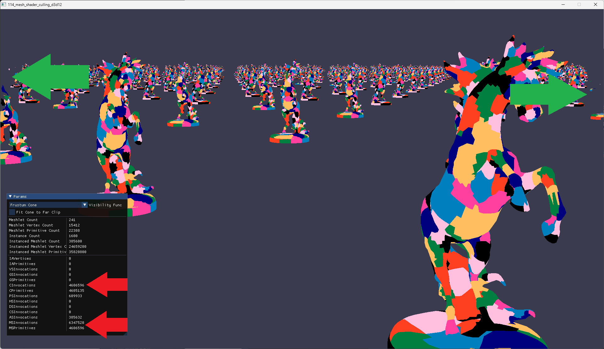
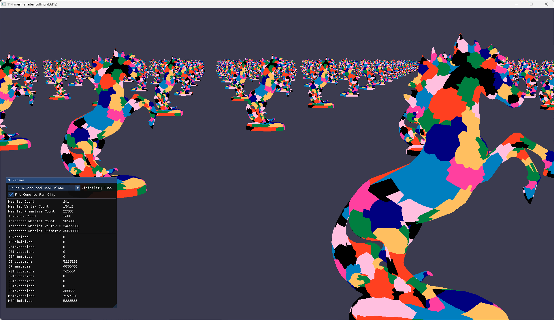
Let’s start by taking a look at what our sample scene looks like unculled.
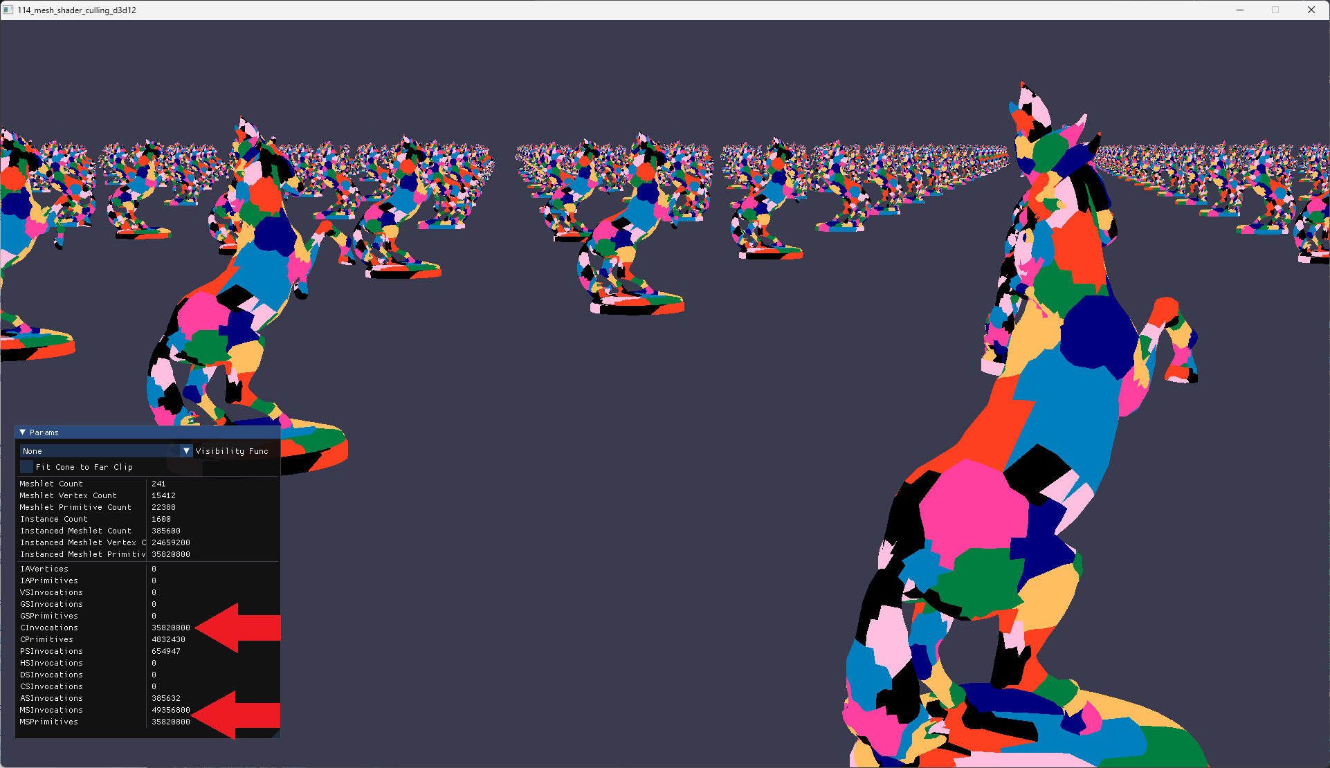
In the screenshot above, I’ve marked 3 statistic values that we’ll pay attention to throughout the remainder of this discussion:
- CInvocations - Number of primitives that were sent to the rasterizer, according to D3D12_QUERY_DATA_PIPELINE_STATISTICS.
- MSInvocations - Number of mesh shaders that are invoked, according to DirectX-Specs: Mesh Shader.
- MSPrimitives - Number of primitives output by a mesh shader, according to DirectX-Specs: Mesh Shader.
With no culling, we have the following values for each statistics:
- CInvocations = 35,820,800
- MSInvocations = 49,356,800
- MSPrimitives = 35,820,800
Where do these numbers come from?
MSPrimitives is straightforward, we just take the meshlet’s primitive count and multiply it by the number of instances: 22,388*1,600=35,820,800.
Since MSPrimitives is the number of primitives the mesh shader sends to the rasterizer, it only makes sense that CInvocations is the same value.
MSInvocations is a bit more invovled. Let’s use a code block to make it easier to read.
// Our code to calculate threadGroupCountX
meshletCount      = 241
instanceCount     = 1,600
threadGroupCountX = ((241 * 1,600) / 32) + 1
threadGroupCountX = (385,600/32) + 1
threadGroupCountX = 12,050 +1
threadGroupCountX = 12,051

// Total amplification shader threads dispatched from C++
totalAmplificationThreads = 12,051 * 32
totalAmplificationThreads = 385,632

// Total mesh shader threads dispatched from amplification shader
totalMeshThreads = 385,632 * 128
totalMeshThreads = 49,360,896
You probably noticed that totalMeshThreads=49,360,896 is close but slightly different form MSInvocations=49,356,800. The difference is 4,096 - where did this come from? It turns out that 385,600 is evenly divisible by 32. So that additional + 1 that’s normally used to round up any fractions is superfluous. So we have 1 amplification shader thread that dispatches 128 mesh shader threads that are all completely out of range for instances and meshlets. Potential optimization opportunity for later.
Now that we have some numbers to work with, lets see what culling can do to slim down these numbers!
Culling Using Frustum Planes
The first frustum based primitive we’ll use for culling are the frustum planes.
We’re going to extract the frustom planes using the geometry of the frustum pyramid, i.e. the vertices near and far clip planes. Extraction is not done using the Gribb and Hartmann method. There’s nothing wrong with the Gribb and Hartmann method, I just wanted the visualizations to line up. I would very much like to revisit the Gribb and Hartmann method in a later post.
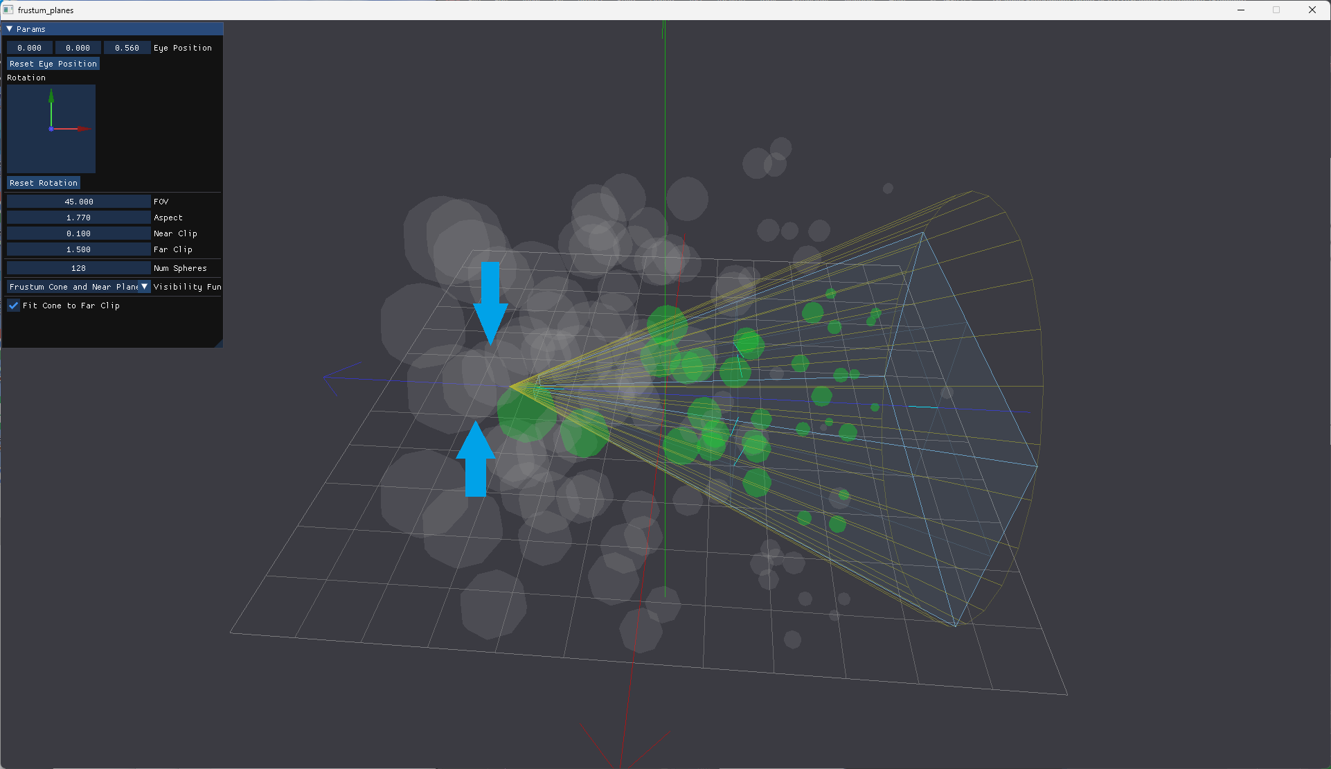
Conceptually, culling using frustum planes looks like the image below.
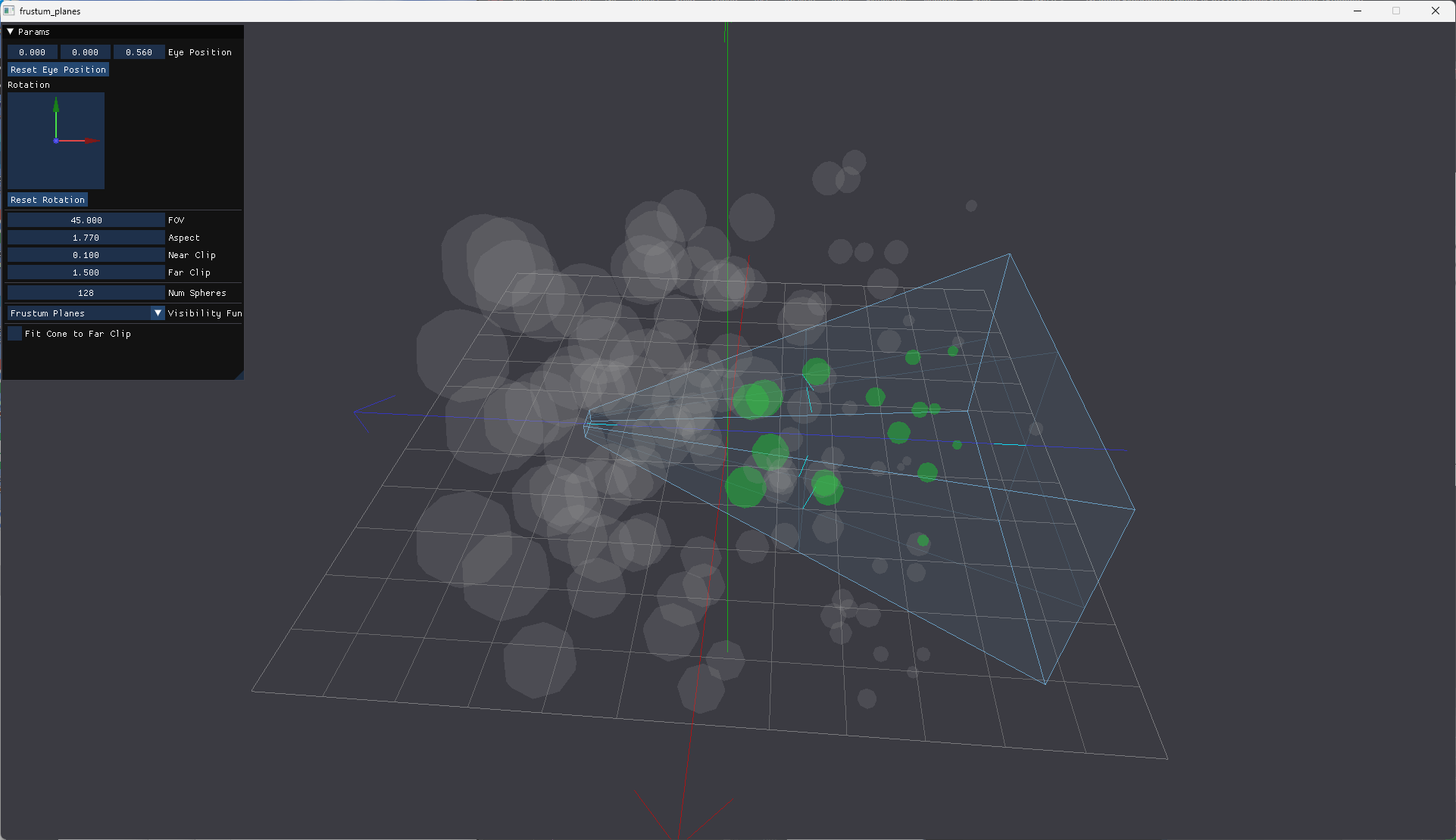
The green spheres have centers completely within the view frustum and are not culled. There gray spheres are either outside the view frustrum or intersects with the planes and are culled. But wait, isn’t that too aggressive? Yes, in the interest of keeping the code simple, I didn’t write code to keep spheres that have negative half space intersections with planes and are close enough to the frustum to be visible. This will result in some artifacts that will be pointed out below. We will also revisit this later post.
The visibility function for frustum planes looks like this (data structures discussed in later section):
float SignedPointPlaneDistance(float3 P, float3 planeN, float3 planeP)
{
    float d = dot(normalize(planeN), P - planeP);
    return d;
};

bool VisibleFrustumPlanes(float4 sphere)
{
    float d0 = SignedPointPlaneDistance(sphere.xyz, Scene.Frustum.Planes[0].Normal, Scene.Frustum.Planes[0].Position);
    float d1 = SignedPointPlaneDistance(sphere.xyz, Scene.Frustum.Planes[1].Normal, Scene.Frustum.Planes[1].Position);
    float d2 = SignedPointPlaneDistance(sphere.xyz, Scene.Frustum.Planes[2].Normal, Scene.Frustum.Planes[2].Position);
    float d3 = SignedPointPlaneDistance(sphere.xyz, Scene.Frustum.Planes[3].Normal, Scene.Frustum.Planes[3].Position);
    float d4 = SignedPointPlaneDistance(sphere.xyz, Scene.Frustum.Planes[4].Normal, Scene.Frustum.Planes[4].Position);
    float d5 = SignedPointPlaneDistance(sphere.xyz, Scene.Frustum.Planes[5].Normal, Scene.Frustum.Planes[5].Position);

    // Determine if we're on the positive half space of frustum planes
    bool pos0 = (d0 >= 0);
    bool pos1 = (d1 >= 0);
    bool pos2 = (d2 >= 0);
    bool pos3 = (d3 >= 0);
    bool pos4 = (d4 >= 0);
    bool pos5 = (d5 >= 0);

    bool inside = pos0 && pos1 && pos2 && pos3 && pos4 && pos5;
    return inside;
}
This code returns true if a meshlet’s bounding sphere’s center is on the positive half space of all 6 planes.
Lets take a look at the numbers and the render artifacts that were mentioned.
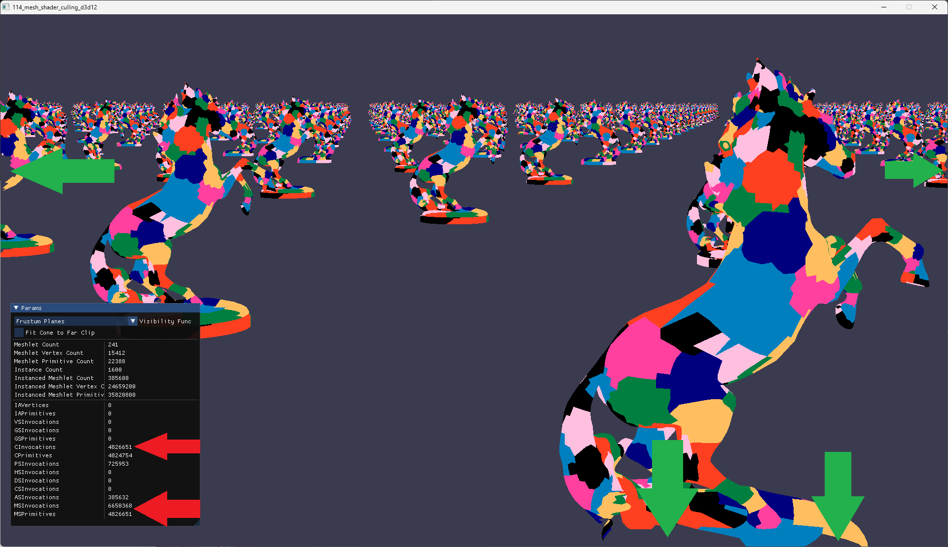
With frustum planes culling, we now have these values:
- CInvocations = 4,826,651
- MSInvocations = 6,650,368
- MSPrimitives = 4,826,651
Pretty good improvement for just some basic culling.
The green arrows point to artifacts that of missing meshlets because their bounding spheres’ centers were not completely inside the frustum. A more robust version of the function could accomodate boundings spheres that are near enough to be visible but their centers are not within the frustum. But we’ll just keep ours simple for now.
Culling Using Frustum Sphere
The next frustum based primitive is a bounding sphere for the frustum.
There’s different ways to derive the center and radius of the frustum’s bounding sphere. BBut again, we’ll keep things simple and just use the longest distance from the center of the frustum center.
Conceptually, culling using the bounding sphere looks like the image below.
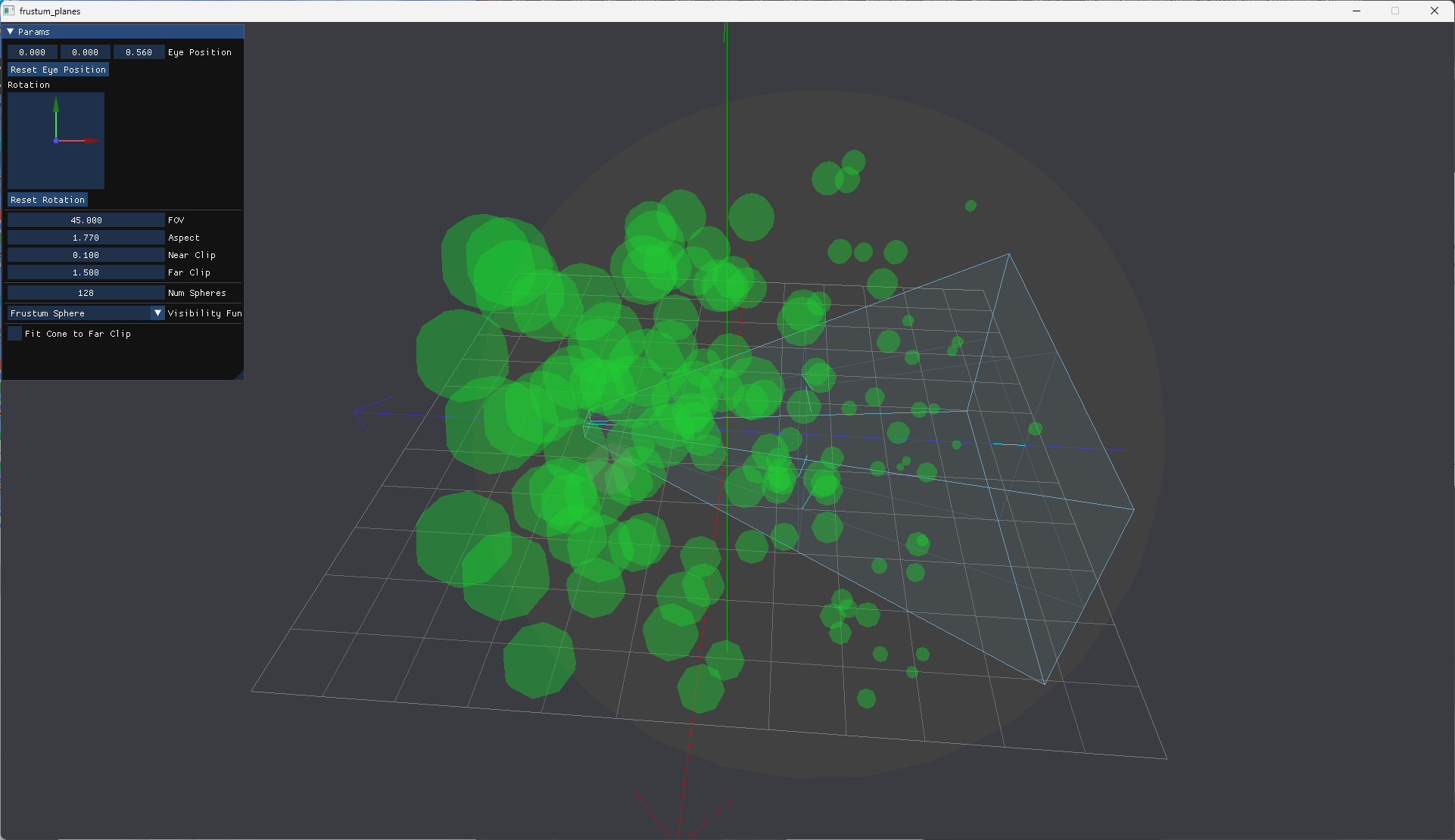
The green spheres intersect the frustum’s bounding sphere and are not culled. There gray spheres dot no intersect the frustum’s bounding sphere and are culled. As you can see, there are many false positives.
The visibility function for frustum bounding sphere looks like this (data structures discussed in later section):
bool VisibleFrustumSphere(float4 sphere)
{
    // Intersection or inside with frustum sphere
    bool inside = (distance(sphere.xyz, Scene.Frustum.Sphere.xyz) < (sphere.w + Scene.Frustum.Sphere.w));
    return inside;
}
This code returns true if the meshlet bounding sphere intersects with the frustum’s bounding sphere.
Lets take a look at the numbers and the render artifacts that were mentioned.
With frustum plane culling, we now have these values:
- CInvocations = 20,454,424
- MSInvocations = 28,184,448
- MSPrimitives = 20,454,424
Better than no culling not nowhere near as good as frustum planes culling.
Because the sphere is so inclusive, there aren’t any missing meshlets artifacts.
Culling Using Frustum Cone
The final frustum based primitive is cone calculated using the FOV angle of the camera.
Conceptually, culling using the frustum cone looks like the image below.
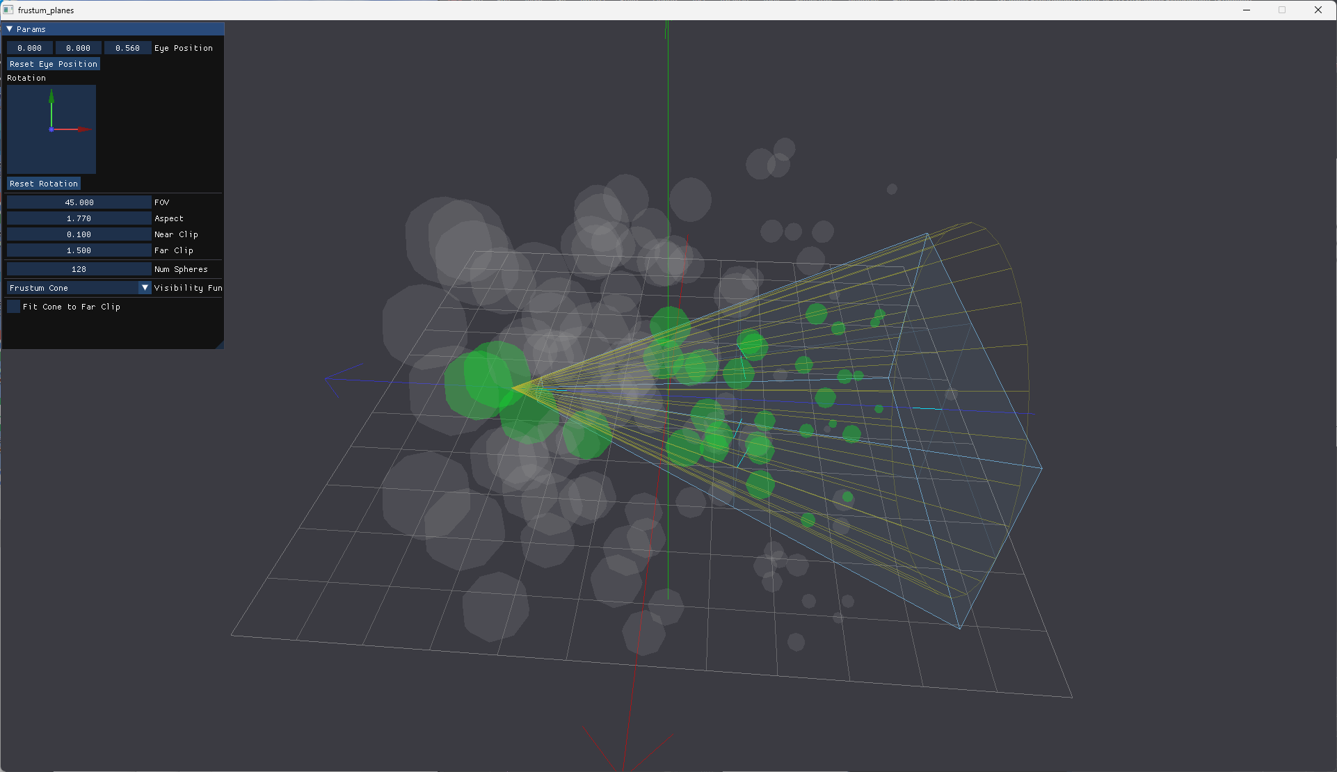
The green spheres intersect the frustum cone and are not culled. There gray spheres dot no intersect the cone and are culled.
The visibility function for frustum cone looks like this (data structures discussed in later section):
bool VisibleFrustumCone(float4 sphere)
{
    // Cone and sphere are within intersectable range
    float3 v0 = sphere.xyz - Scene.Frustum.Cone.Tip;
    float  d0 = dot(v0, Scene.Frustum.Cone.Direction);
    bool   i0 = (d0 <= (Scene.Frustum.Cone.Height + sphere.w));

    float cs = cos(Scene.Frustum.Cone.Angle * 0.5);
    float sn = sin(Scene.Frustum.Cone.Angle * 0.5);
    float a  = dot(v0, Scene.Frustum.Cone.Direction);
    float b  = a * sn / cs;
    float c  = sqrt(dot(v0, v0) - (a * a));
    float d  = c - b;
    float e  = d * cs;
    bool  i1 = (e < sphere.w);

    return i0 && i1;
}
This code returns true if the meshlet bounding sphere intersects with the frustum cone.
However, if we take a look at the render, we notice an issue immediately.
The missing meshlet artifact is back. It looks like our cone angle was too small and meshlets towards frustum corners are being culled.
Initially, the cone’s used the FOV angle, in our currently implementation we use a horizontal field of view. So the cone’s radius is half of the width of the far plane. This fits the cone to the longest edges of the frustum. While this is sufficient coverage for the edges, it leaves out the corner.
So easy fix, just fit the cone to the one of the corners of the far plane.
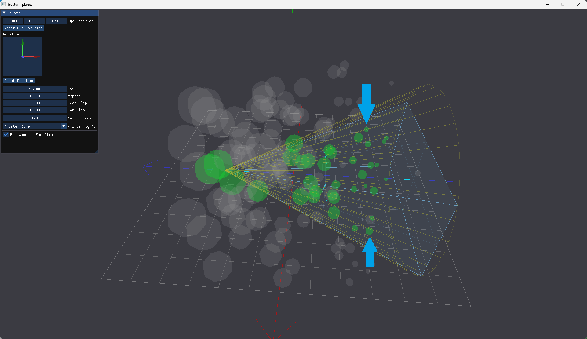
Problem solved. No more missing meshlets. The blue arrows blue arrow point to examples of spheres that were culled when the cone wasn’t fitted to a corner of the far plane.
Here’s what the fitting code looks like in the camera class:
PerspCamera::FrustumCone PerspCamera::GetFrustumCone(bool fitFarClip) const
{
    PerspCamera::FrustumCone cone = {};
    cone.Tip                      = mEyePosition;
    cone.Dir                      = mViewDirection;
    cone.Height                   = mFarClip;
    cone.Angle                    = glm::radians((mAspect > 1.0) ? mHorizFovDegrees : mVertFovDegrees);

    if (fitFarClip) {
        // View projection matrix
        auto& VP    = this->GetViewProjectionMatrix();
        // Inverse view projection matrix
        auto  invVP = glm::inverse(VP);
        // Clip space coordinates
        auto csFarTL = glm::vec3(-1, 1, 1);
        auto csFarBL = glm::vec3(-1, -1, 1);
        auto csFarBR = glm::vec3(1, -1, 1);
        auto csFarTR = glm::vec3(1, 1, 1);
        // Transform into view coordinates using inverse view projection matrix
        auto farTL = invVP * glm::vec4(csFarTL, 1.0f);
        auto farBL = invVP * glm::vec4(csFarBL, 1.0f);
        auto farBR = invVP * glm::vec4(csFarBR, 1.0f);
        auto farTR = invVP * glm::vec4(csFarTR, 1.0f);
        // Divide to finalize unproject
        farTL /= farTL.w;
        farBL /= farBL.w;
        farBR /= farBR.w;
        farTR /= farTR.w;
        // Find center of far clip plane
        auto farCenter = (farTL + farBL + farBR + farTR) / 4.0f;
        // Distance from far clip plane center to top left corner of far clip plane
        float r    = glm::distance(farCenter, farTL);
        // Calculate angle using arctan
        cone.Angle = 2.0f * atan(r / mFarClip);
    }
    return cone;
}
Here’s the render with the cone fitted to a corner of the far plane.
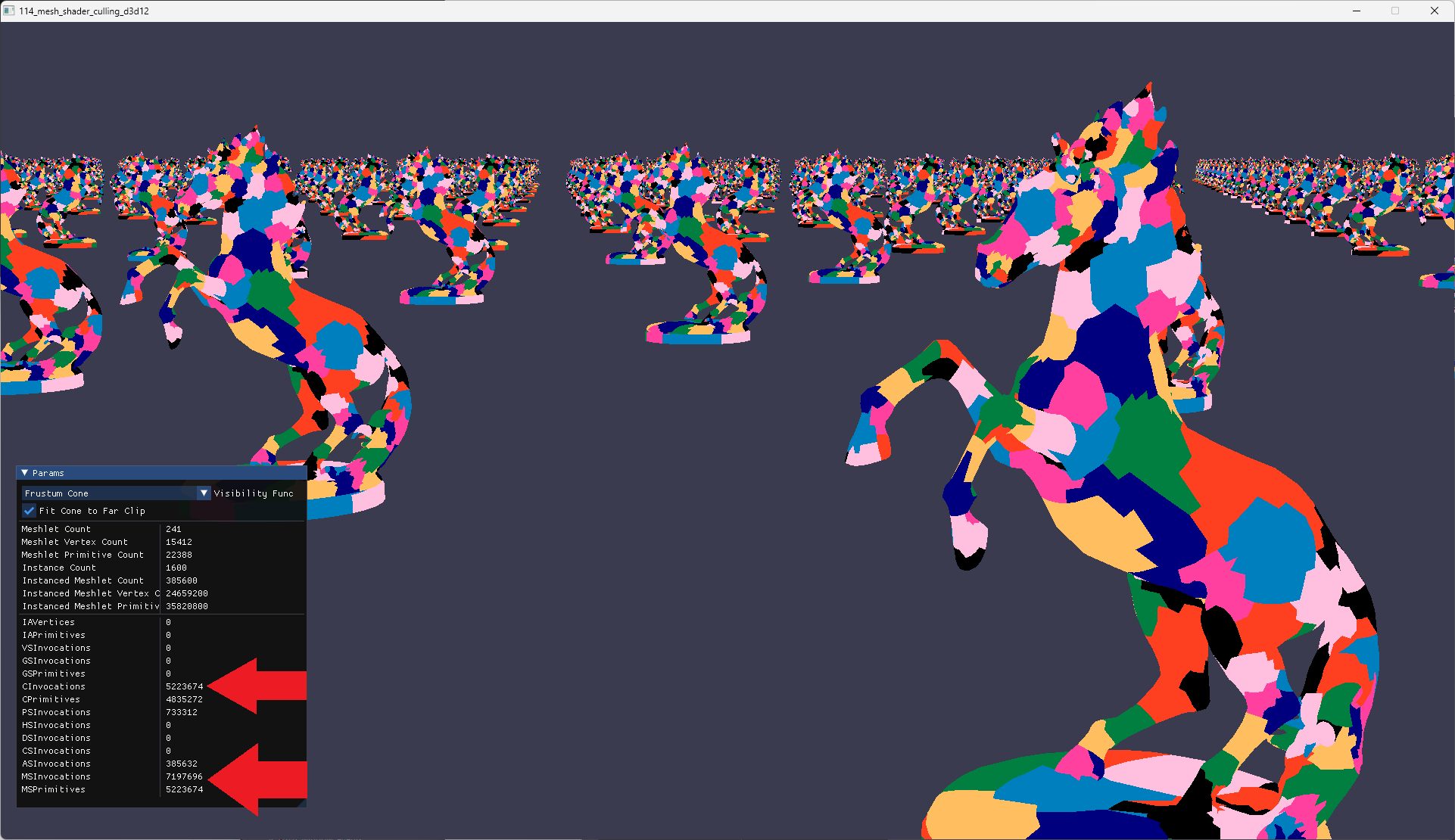
No more missing meshlets artifacts!
With frustum plane culling, we now have these values:
- CInvocations = 5,223,674
- MSInvocations = 7,197,696
- MSPrimitives = 5,223,674
These values are just a tad higher than culling using frustum planes, but significantly better than culling using the frustum’s bounding sphere.
Culling Using Frustum Cone And Near Plane
For the truly pedantic, there may be suspicion of possible false positives behind the near clip plane. This does actually happen. The of the cone extends past the near clip plane behind the camera. This can cause the cone to intersect with meshlet bounding spheres that aren’t actually visible. Depending on the case, the cost of processing these meshlets may be undesirable.
How do we prevent this?
We combine the cone culling and partial frustum plane culling.
The blue arrows point to the two spheres that are culled if we combined the the two culling methods.
The visibility function for combined culling methods looks like this (data structures discussed in later section):
bool VisibleFrustumConeAndNearPlane(float4 sphere)
{
    bool i0 = VisibleFrustumCone(sphere);

    FrustumPlane frNear = Scene.Frustum.Planes[FRUSTUM_PLANE_NEAR];
    float d0 = SignedPointPlaneDistance(sphere.xyz, frNear.Normal, frNear.Position);
    bool  i1 = (abs(d0) < sphere.w); // Intersects with near plane
    bool  i2 = (d0 > 0);             // On positive half space of near plane

    return i0 && (i1 || i2);
}
This code returns true if the meshlet bounding sphere intersects with the frustum cone and (the meshlet bounding sphere intersects with or is on the positive half space of the the near clip plane).
Here’s the render with the combined culling methods. Virtually no difference for our sample case. But deep in our pedantic hearts, we know it could one day possibly, maybe, make a difference.
I won’t bother going over the numbers here. I’m pretty sure the positioning of the horse statue doesn’t put anything close enough to the near clip plane to matter. Any differences in the values could simply be due to the rotation of some of the horse statues.
C++ Changes
New Enums And Structs
enum
{
    FRUSTUM_PLANE_LEFT   = 0,
    FRUSTUM_PLANE_RIGHT  = 1,
    FRUSTUM_PLANE_TOP    = 2,
    FRUSTUM_PLANE_BOTTOM = 3,
    FRUSTUM_PLANE_NEAR   = 4,
    FRUSTUM_PLANE_FAR    = 5,
};

struct FrustumPlane
{
    float3 Normal;
    float  __pad0;
    float3 Position;
    float  __pad1;
};

struct FrustumCone
{
    float3 Tip;
    float  Height;
    float3 Direction;
    float  Angle;
};

struct FrustumData
{
    FrustumPlane Planes[6];
    float4       Sphere;
    FrustumCone  Cone;
};

struct SceneProperties
{
    float4x4    CameraVP;
    FrustumData Frustum;
    uint        InstanceCount;
    uint        MeshletCount;
    uint        VisibilityFunc;
};
We introduce a new enum and a few new structs to store the various frustum based primitives. SceneProperties has two new members Frustum and VisibilityFunc to store the frustum data and the visibility function, respectively.
Increasing the Number Of Instances
const uint32_t        kNumInstanceCols = 40;
const uint32_t        kNumInstanceRows = 40;
std::vector<float4x4> instances(kNumInstanceCols * kNumInstanceRows);
As mentioned above, we increased the number of instances so we can show the effects of the culling when the camera is rotated.
Changing Location of instances
float farDist = 1000.0f;
{
    float maxSpan       = std::max<float>(meshBounds.Width(), meshBounds.Depth());
    float instanceSpanX = 4.0f * maxSpan;
    float instanceSpanZ = 4.5f * maxSpan;
    float totalSpanX    = kNumInstanceCols * instanceSpanX;
    float totalSpanZ    = kNumInstanceRows * instanceSpanZ;

    farDist = std::min(totalSpanX, totalSpanZ);

    for (uint32_t j = 0; j < kNumInstanceRows; ++j)
    {
        for (uint32_t i = 0; i < kNumInstanceCols; ++i)
        {
            float x = i * instanceSpanX - (totalSpanX / 2.0f) + instanceSpanX / 2.0f;
            float y = 0;
            float z = j * instanceSpanZ - (totalSpanZ / 2.0f) + instanceSpanZ / 2.0f;

            uint32_t index   = j * kNumInstanceCols + i;
            float    t       = static_cast<float>(glfwGetTime()) + ((i ^ j + i) / 10.0f);
            instances[index] = glm::translate(float3(x, y, z)) * glm::rotate(t, float3(0, 1, 0));
        }
    }
}
The positioning of the instances had to change a bit to accomodate the camera being placed in the center.
Uploading The Scene’s Constant Buffer
float3 eyePosition = float3(0, 0.2f, 0.0f);
float3 target      = float3(0, 0.0f, -1.3f);

// Smooth out the rotation on Y
gAngle += (gTargetAngle - gAngle) * 0.1f;
mat4 rotMat = glm::rotate(glm::radians(gAngle), float3(0, 1, 0));
target      = rotMat * float4(target, 1.0);

PerspCamera camera = PerspCamera(45.0f, window->GetAspectRatio(), 0.1f, farDist);
camera.LookAt(eyePosition, target);

Camera::FrustumPlane frLeft, frRight, frTop, frBottom, frNear, frFar;
camera.GetFrustumPlanes(&frLeft, &frRight, &frTop, &frBottom, &frNear, &frFar);
//
auto frCone = camera.GetFrustumCone(gFitConeToFarClip);

scene.CameraVP                             = camera.GetViewProjectionMatrix();
scene.Frustum.Planes[FRUSTUM_PLANE_LEFT]   = {frLeft.Normal, 0.0f, frLeft.Position, 0.0f};
scene.Frustum.Planes[FRUSTUM_PLANE_RIGHT]  = {frRight.Normal, 0.0f, frRight.Position, 0.0f};
scene.Frustum.Planes[FRUSTUM_PLANE_TOP]    = {frTop.Normal, 0.0f, frTop.Position, 0.0f};
scene.Frustum.Planes[FRUSTUM_PLANE_BOTTOM] = {frBottom.Normal, 0.0f, frBottom.Position, 0.0f};
scene.Frustum.Planes[FRUSTUM_PLANE_NEAR]   = {frNear.Normal, 0.0f, frNear.Position, 0.0f};
scene.Frustum.Planes[FRUSTUM_PLANE_FAR]    = {frFar.Normal, 0.0f, frFar.Position, 0.0f};
scene.Frustum.Sphere                       = camera.GetFrustumSphere();
scene.Frustum.Cone.Tip                     = frCone.Tip;
scene.Frustum.Cone.Height                  = frCone.Height;
scene.Frustum.Cone.Direction               = frCone.Dir;
scene.Frustum.Cone.Angle                   = frCone.Angle;
scene.InstanceCount                        = static_cast<uint32_t>(instances.size());
scene.MeshletCount                         = static_cast<uint32_t>(meshlets.size());
scene.VisibilityFunc                       = gVisibilityFunc;
Just a couple of small changes to the scene data. Rotation is applied to the camera when there’s left drag on the mouse. The frustum data and visibility function are updated. The various visibility functions are selectable at runtime.
Descriptor Changes
// -----------------------------------------------------------------------------
// Direct3D
// -----------------------------------------------------------------------------
commandList->SetGraphicsRootConstantBufferView(0, sceneBuffer->GetGPUVirtualAddress());
commandList->SetGraphicsRootShaderResourceView(1, positionBuffer->GetGPUVirtualAddress());
commandList->SetGraphicsRootShaderResourceView(2, meshletBuffer->GetGPUVirtualAddress());
commandList->SetGraphicsRootShaderResourceView(3, meshletBoundsBuffer->GetGPUVirtualAddress()); // **NEW**
commandList->SetGraphicsRootShaderResourceView(4, meshletVerticesBuffer->GetGPUVirtualAddress());
commandList->SetGraphicsRootShaderResourceView(5, meshletTrianglesBuffer->GetGPUVirtualAddress());
commandList->SetGraphicsRootShaderResourceView(6, instancesBuffer->GetGPUVirtualAddress());

// -----------------------------------------------------------------------------
// Metal
// -----------------------------------------------------------------------------
pRenderEncoder->setObjectBytes(&scene, sizeof(SceneProperties), 0);
pRenderEncoder->setObjectBuffer(meshletBoundsBuffer.Buffer.get(), 0, 1); // **NEW**
pRenderEncoder->setObjectBuffer(instancesBuffer.Buffer.get(), 0, 2);

// -----------------------------------------------------------------------------
// Vulkan
// -----------------------------------------------------------------------------
PushGraphicsDescriptor(CommandBuffer, pipelineLayout, 0, 0, VK_DESCRIPTOR_TYPE_UNIFORM_BUFFER, &sceneBuffer);
PushGraphicsDescriptor(CommandBuffer, pipelineLayout, 0, 1, VK_DESCRIPTOR_TYPE_STORAGE_BUFFER, &positionBuffer);
PushGraphicsDescriptor(CommandBuffer, pipelineLayout, 0, 2, VK_DESCRIPTOR_TYPE_STORAGE_BUFFER, &meshletBuffer);
PushGraphicsDescriptor(CommandBuffer, pipelineLayout, 0, 3, VK_DESCRIPTOR_TYPE_STORAGE_BUFFER, &meshletBoundsBuffer); // **NEW**
PushGraphicsDescriptor(CommandBuffer, pipelineLayout, 0, 4, VK_DESCRIPTOR_TYPE_STORAGE_BUFFER, &meshletVerticesBuffer);
PushGraphicsDescriptor(CommandBuffer, pipelineLayout, 0, 5, VK_DESCRIPTOR_TYPE_STORAGE_BUFFER, &meshletTrianglesBuffer);
PushGraphicsDescriptor(CommandBuffer, pipelineLayout, 0, 6, VK_DESCRIPTOR_TYPE_STORAGE_BUFFER, &instancesBuffer);
Just a one line change to add a descriptor update for meshletBoundsBuffer.
Amplification Shader Changes
enum {
    FRUSTUM_PLANE_LEFT   = 0,
    FRUSTUM_PLANE_RIGHT  = 1,
    FRUSTUM_PLANE_TOP    = 2,
    FRUSTUM_PLANE_BOTTOM = 3,
    FRUSTUM_PLANE_NEAR   = 4,
    FRUSTUM_PLANE_FAR    = 5,
};

enum VisibilityFunc
{
    VISIBILITY_FUNC_NONE                = 0,
    VISIBILITY_FUNC_PLANES              = 1,
    VISIBILITY_FUNC_SPHERE              = 2,
    VISIBILITY_FUNC_CONE                = 3,
    VISIBILITY_FUNC_CONE_AND_NEAR_PLANE = 4,
};

struct FrustumPlane {
    float3 Normal;
    float  __pad0;
    float3 Position;
    float  __pad1;
};

struct FrustumCone {
    float3 Tip;
    float  Height;
    float3 Direction;
    float  Angle;
};

struct FrustumData {
    FrustumPlane  Planes[6];
    float4        Sphere;
    FrustumCone   Cone;
};

struct SceneProperties {
    float4x4    CameraVP;
    FrustumData Frustum;
    uint        InstanceCount;
    uint        MeshletCount;
    uint        VisibilityFunc;
};
Identical to the C++ changes, we introduce a new enum and a few new structs for the various frustum based primitives. SceneProperties has two new members Frustum and VisibilityFunc to allow us to access frustum data and the visibility function, respectively.
Meshlet Bounds Buffers
// -----------------------------------------------------------------------------
// HLSL
// -----------------------------------------------------------------------------
StructuredBuffer<float4> MeshletBounds : register(t3);

// -----------------------------------------------------------------------------
// MSL
// -----------------------------------------------------------------------------
device const float4*  MeshletBounds [[buffer(1)]],
Shader resource for MeshletBounds buffer.
Using Visibility Functions
HLSL for D3D12 and Vulkan
[numthreads(AS_GROUP_SIZE, 1, 1)]
void asmain(
    uint gtid : SV_GroupThreadID,
    uint dtid : SV_DispatchThreadID,
    uint gid  : SV_GroupID
)
{
    bool visible = false;

    uint instanceIndex = dtid / Scene.MeshletCount;
    uint meshletIndex  = dtid % Scene.MeshletCount;

    if ((instanceIndex < Scene.InstanceCount) && (meshletIndex < Scene.MeshletCount)) {
        // Transform meshlet's bounding sphere into world space
        float4x4 M = Instances[instanceIndex].M;
        float4 meshletBoundingSphere = mul(M, float4(MeshletBounds[meshletIndex].xyz, 1.0));
        meshletBoundingSphere.w = MeshletBounds[meshletIndex].w;

        if (Scene.VisibilityFunc == VISIBILITY_FUNC_NONE) {
            visible = true;
        }
        else if (Scene.VisibilityFunc == VISIBILITY_FUNC_PLANES) {
            visible = VisibleFrustumPlanes(meshletBoundingSphere);
        }
        else if (Scene.VisibilityFunc == VISIBILITY_FUNC_SPHERE) {
            visible = VisibleFrustumSphere(meshletBoundingSphere);
        }
        else if (Scene.VisibilityFunc == VISIBILITY_FUNC_CONE) {
            visible = VisibleFrustumCone(meshletBoundingSphere);
        }
        else if (Scene.VisibilityFunc == VISIBILITY_FUNC_CONE_AND_NEAR_PLANE) {
            visible = VisibleFrustumConeAndNearPlane(meshletBoundingSphere);
        }
    }

    if (visible) {
        uint index = WavePrefixCountBits(visible);
        sPayload.InstanceIndices[index] = instanceIndex;
        sPayload.MeshletIndices[index]  = meshletIndex;
    }

    uint visibleCount = WaveActiveCountBits(visible);
    DispatchMesh(visibleCount, 1, 1, sPayload);
}
MSL for Metal
[[object]]
void objectMain(
    constant SceneProperties&  Scene         [[buffer(0)]],
    device const float4*       MeshletBounds [[buffer(1)]],
    device const Instance*     Instances     [[buffer(2)]],
    uint                       gtid          [[thread_position_in_threadgroup]],
    uint                       dtid          [[thread_position_in_grid]],
    object_data Payload&       outPayload    [[payload]],
    mesh_grid_properties       outGrid)
{
    uint visible = 0;

    uint instanceIndex = dtid / Scene.MeshletCount;
    uint meshletIndex  = dtid % Scene.MeshletCount;

    if ((instanceIndex < Scene.InstanceCount) && (meshletIndex < Scene.MeshletCount)) {
        // Transform meshlet's bounding sphere into world space
        float4x4 M = Instances[instanceIndex].M;
        float4 meshletBoundingSphere = M * float4(MeshletBounds[meshletIndex].xyz, 1.0);
        meshletBoundingSphere.w = MeshletBounds[meshletIndex].w;

        if (Scene.VisibilityFunc == VISIBILITY_FUNC_NONE) {
            visible = 1;
        }
        else if (Scene.VisibilityFunc == VISIBILITY_FUNC_PLANES) {
            visible = VisibleFrustumPlanes(Scene, meshletBoundingSphere) ? 1 : 0;
        }
        else if (Scene.VisibilityFunc == VISIBILITY_FUNC_SPHERE) {
            visible = VisibleFrustumSphere(Scene, meshletBoundingSphere) ? 1 : 0;
        }
        else if (Scene.VisibilityFunc == VISIBILITY_FUNC_CONE) {
            visible = VisibleFrustumCone(Scene, meshletBoundingSphere) ? 1 : 0;
        }
        else if (Scene.VisibilityFunc == VISIBILITY_FUNC_CONE_AND_NEAR_PLANE) {
            visible = VisibleFrustumConeAndNearPlane(Scene, meshletBoundingSphere) ? 1 : 0;
        }
    }

    if (visible) {
        uint index = simd_prefix_exclusive_sum(visible);
        outPayload.InstanceIndices[index] = instanceIndex;
        outPayload.MeshletIndices[index]  = meshletIndex;
    }

    // Assumes all meshlets are visible
    uint visibleCount = simd_sum(visible);
    if (gtid == 0) {
        outGrid.set_threadgroups_per_grid(uint3(visibleCount, 1, 1));
    }
}
There’s now a large chunk of code for visibility determination in the amplification shader after the range checking of instanceIndex and meshletIndex.
As mentioned earlier, before we do any visibility determination using the meshlet’s bounding sphere, we need to transform it into world space:
    float4x4 M = Instances[instanceIndex].M;
    float4 meshletBoundingSphere = M * float4(MeshletBounds[meshletIndex].xyz, 1.0);
    meshletBoundingSphere.w = MeshletBounds[meshletIndex].w;
The if/else if chunk is straightforward, I’ll trust you can grok it easily.
Mesh Shader Changes
There aren’t any mesh shader changes for this post. Hope it’s not too disappointing. We’ll make up for it soon.
Full Shader Source
Here are links to the HLSL and MSL: