First published: 2024-01-24
Last updated: 2024-01-27
About the Mesh Shading Series
This post is part 1 of a series about mesh shading. My intent in this series is to introduce the various parts of mesh shading in an easy to understand fashion. Well, as easy as I can make it. My objective isn’t to convince you to use mesh shading. I assume you’re reading this post because you’re already interested in mesh shading. Instead, my objective is to explain the mechanics of how to do mesh shading in Direct3D 12, Metal, and Vulkan as best I can. My hope is that you’re able to use this information in your own graphics projects and experiments.
- Mesh Shading Part 1: Rendering Meshlets
- Mesh Shading Part 2: Amplification
- Mesh Shading Part 3: Instancing
- Mesh Shading Part 4: Culling
- Mesh Shading Part 5: LOD Selection
- Mesh Shading Part 6: LOD Calculation
- Mesh Shading Part 7: Culling + LOD
- Mesh Shading Part 8: Vertex Attributes (TBD)
- Mesh Shading Part 9: Barycentric Interpolation (TBD)
Sample Projects for This Post
110_mesh_shader_triangle - Do the lights turn on? Demonstrates the most absolute basic functionality of a mesh shader.
111_mesh_shader_meshlets - Demonstrates how to use meshopt to create meshlets and render them using mesh and pixel/fragment shaders.
Terminology
These will be covered in more detail in the following sections and later posts. I wanted to put these here because they’re often used interchangeably. There doesn’t really seem to be any rhyme or reason as to why there’s so many variations of the same word. Even some of the graphics API documentation is inconsistent with which set of words is used.
workgroup / threadgroup / work group / thread group / work-group / thread-group
A single unit of work that the CPU dispatches to the GPU.
We will use workgroup or threadgroup.
workgroup count / threadgroup count / (apply the other prefix variations )
The number of units of work that the CPU dispatches to the GPU.
workgroup size / threadgroup size / (apply the other prefix variations)
The number of threads within a workgroup or threadgroup.
Introduction
Don’t be sad, but I’m going to skip over the introduction to mesh shaders because there’s already a bunch of articles and posts about that. I don’t think I can add much to that part of the discussion. So, if you haven’t been formally introduced to mesh shading yet, here’s a few articles that I recommend:
- DirectX Developer Blog: Mesh Shaders and Amplification Shaders
- NVIDIA Developer Technical Blog: Introduction to Turing Mesh Shaders
- Geeks3D: Quick Introduction to Mesh Shaders
- Timur’s Blog: Mesh and task shaders intro and basics
- Metal By Example: Mesh Shaders and Meshlet Culling in Metal 3
Now that you’re acquainted with mesh shading and its accompanying concepts, let’s get to the code! The following posts show basic setup for mesh shading for each API:
- Direct3D 12
- Metal (TBD)
- Vulkan
Each of the above posts walks through a basic “do the lights turn on” project for mesh shading by rendering a simple triangle with vertex colors. A few things can be observed when looking over the code for any of the graphics APIs:
- Vertex input information (vertex bindings and vertex attribute descriptions) is not provided for the graphics pipeline.
- Input assembly (topology) is not provided for the graphics pipeline.
- Vertex shader stage is not provided for the graphics pipeline.
As mentioned in every article about mesh shading, the above are some of the changes when moving from the traditional graphics pipeline to a mesh shader graphics pipeline. All the geometry shader stages are replaced with a mesh shader stage and optionally an amplification shader stage. There’s much ado about the optionality of the amplification stage, but in practice mesh shading has very limited use without amplification.
For simplicity, I’m just going to use the term amplification to refer to the stage that comes before the mesh shader stage. Each of the 3 graphics APIs has a different name for this stage: amplification shader stage (D3D12), task shader stage (Vulkan), and object function (Metal).
Also mentioned in every article about mesh shading is that the functionality of the traditional geometry stages is now divided between the amplification shader and the mesh shader. We’ll get to amplification soon enough, for now let’s take a look at some functionality that’s covered by the mesh shader.
HLSL for Direct3D and Vulkan
struct MeshOutput {
    float4 Position : SV_POSITION;
    float3 Color    : COLOR;
};

[outputtopology("triangle")]
[numthreads(1, 1, 1)]
void msmain(out indices uint3 triangles[1], out vertices MeshOutput vertices[3]) {
    // Must be called before writing the geometry output
    SetMeshOutputCounts(3, 1); // 3 vertices, 1 primitive

    triangles[0] = uint3(0, 1, 2);

    vertices[0].Position = float4(-0.5, 0.5, 0.0, 1.0);
    vertices[0].Color = float3(1.0, 0.0, 0.0);

    vertices[1].Position = float4(0.5, 0.5, 0.0, 1.0);
    vertices[1].Color = float3(0.0, 1.0, 0.0);

    vertices[2].Position = float4(0.0, -0.5, 0.0, 1.0);
    vertices[2].Color = float3(0.0, 0.0, 1.0);
}
MSL for Metal
#include <metal_stdlib>
using namespace metal;

struct Vertex {
	float4 PositionCS [[position]];
	float3 Color;
};

// metal::mesh<V, P, NV, NP, t>
//  V  - vertex type (output struct)
//  P  - primitive type (output struct)
//  NV - max number of vertices
//  NP - max number of primitives
//  t  - topology
using Mesh = metal::mesh<Vertex, void, 3, 1, topology::triangle>;

[[mesh]]
void meshMain(Mesh outMesh)
{
    outMesh.set_primitive_count(3);

    Vertex vertices[3];

    vertices[0].PositionCS = float4(-0.5, 0.5, 0.0, 1.0);
    vertices[0].Color = float3(1.0, 0.0, 0.0);

    vertices[1].PositionCS = float4(0.5, 0.5, 0.0, 1.0);
    vertices[1].Color = float3(0.0, 1.0, 0.0);

    vertices[2].PositionCS = float4(0.0, -0.5, 0.0, 1.0);
    vertices[2].Color = float3(0.0, 0.0, 1.0);

    outMesh.set_vertex(0, vertices[0]);
    outMesh.set_vertex(1, vertices[1]);
    outMesh.set_vertex(2, vertices[2]);

    outMesh.set_index(0, 0);
    outMesh.set_index(1, 1);
    outMesh.set_index(2, 2);
}
Similar to a vertex shader, a mesh shader also must define an output. Unlike a vertex shader, a mesh shader defines its own output topology.
The above mesh shader does the following:
- Defines the number of threads for each shader workgroup (aka threadgroup) of this mesh shader (D3D12 and Vulkan - Metal does this on the API side)
- Defines output topology
- Defines the number of output primitives
- Defines the number of output vertices and indices (we’ll see later these are maximum values)
- Defines what the vertex output looks like
- Sets the output primitive count
- Sets the output vertex count
- Writes out vertex data
- Writes out index data
The output of the mesh shader goes into the rasterizer which feeds into the pixel/fragment shader.
If we take this shader and pair it with a pixel/fragment shader in a graphics pipeline, we can call/dispatch it from the API side with just a single threadgroup:
// D3D12
DispatchMesh(1, 1, 1);

// Metal
drawMeshThreadgroups(
    MTL::Size(1, 1, 1),  // threadgroupsPerGrid         (threadgroup count)
    MTL::Size(0, 0, 0),  // threadsPerObjectThreadgroup (size of amplification shader threadgroup)
    MTL::Size(1, 1, 1)); // threadsPerMeshThreadgroup   (size of mesh shader threadgroup)

// Vulkan
vkCmdDrawMeshTasksEXT(commandBuffer, 1, 1, 1);
There’s a few things about the above example that’s a bit misleading, we’ll sort it all that out in the next example, but the main ideas here are:
- this shader can run without any additional input
- lets us see that the most basic version of the a mesh shader based graphics pipeline works
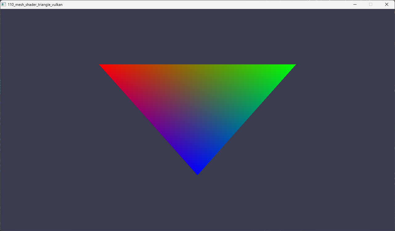
The 110_mesh_shader sample renders this image using the above shader:
API Differences
There’s some differences, beyond the obvious, that are worth noting in case you’re working in some combination of D3D12/Vulkan and Metal:
- D3D12 and Vulkan both set the size of the threadgroup from the shader whereas this happens on the API side for Metal.
- HLSL and MSL have very different ways of defining output information for topology, primitives and vertices.
Wrapping Up Introduction
In this section, we covered the very basics of how to get started with mesh shading. Hopefully you agree that it’s relatively straightforward. Even though there are some minor differences, the overall approach is more or less the same on all 3 APIs.
Make Them Meshlets!
meshopt is used throughout this post series because it’s easy to work with and widely accepted as the industry solution for all of one’s mesh optimization needs.
For simplicity, I’m going to use the NVIDIA suggested values for the max vertices (64) and max triangles (124) when creating meshlets. If you’re after something more optimal, just change them to suggested values of your target GPU. Yes, I’m aware the suggested max triangles value is actually 126, 124 is used here since meshopt wants a value that’s 4 aligned.
What Is A Meshlet?
From Mesh Shaders and Amplification Shaders: Reinventing the Geometry Pipeline: a meshlet is a subset of a mesh created through an intentional partition of the geometry.
Please allow me to try and add some detail. Let’s say we have a triangle mesh of a horse statue. We then take this mesh and divide it up into smaller regions. Each of these regions has some number of triangles and some number of vertices. Normally, the triangles in each region are connected. But sometimes there may be some triangles that are very near but not connected.
Since we’re working with GPUs, there’s always limits, we want to apply some limits to the number of triangles and vertices that each region can have. So, let’s say we want each region to have a maximum of 124 triangles. These 124 triangles need to be made up of a maximum of 64 vertices. It’s okay for us to have fewer of either triangles or vertices, but a region can never exceed 124 triangles or 64 vertices. For example:
- ✅ A region with 96 triangles and 64 vertices is okay
- ✅ A region with 124 triangles and 48 vertices is okay
- ✅ A region with 96 triangles and 48 vertices is okay
- ❌ A region with 128 triangles and 64 vertices is not okay
- ❌ A region with 124 triangles and 72 vertices is not okay
- ❌ A region with 128 triangles and 72 vertices is not okay
You get the idea. And of course, a region is a meshlet.
The maximum number of triangles and vertices are defined by a GPU. It should be noted that these maximum values aren’t hard set. There’s usually a range, and it’s within this range that the GPU can efficiently process the triangles - depending on the use case. But let’s focus on one concrete example.
NVIDIA’s recommends 126 triangles and 64 vertices for general cases. To achieve maximum performance efficiency we want the regions to have 126 triangles and 64 vertices. Exceeding these values generally results in a performance penalty. Being under these values generally means the GPU isn’t utilized efficiently. We’re close enough to 126 with 124, hopefully no one will throw rocks at us.
That said, in practice, sometimes meshlet generators will generate meshlets with triangle and vertex counts that are under the maximum values specified. If you’re shipping something for real, this wouldn’t be ideal and you’d want to optimize this. However, for our easy to understand meshlet post series here, being well under the maximum values is perfectly fine.
Going back to our meshlets of 124 triangles and 64 vertices, we might wonder, “how are these meshlets stored?” Our answer to this is based on what meshopt outputs. I’m by no means saying it’s the only answer, there are certainly different approaches. But for simplicity, we’re going with what makes sense for the tools we’re using.
For each meshlet, we’re going to store the following:
- a list of vertex indices mappings
- a set of indices that define the triangles in the meshlet
Using vertex position as an example, the mesh shader will use the list of vertex indices to read the vertex position for processing. For example, if this list contains 124 entries, the mesh shader will use each entry’s value to locate the vertex position from the input, process the vertex position, then write the result to the mesh shader’s vertex output.
The set of indices that define the triangle in the meshlet are pretty literal. The triangle’s indices index into the mesh shader’s vertex output further down the pipeline. To be clear, the indices refer to the mesh shader’s vertex output that we said was written out in the paragraph right before this one.
The following is conceptual code to try and make it easier to understand. We’ll see what this looks like in practice in the following sections.
#define kMaxTriangles 124
#define kMaxVertices  64

struct Mesh {
    std::vector<vec3> vertexPositions;
}

struct MeshletTriangle {
    int vertexIndex0; // indexes meshlet's output vertex positions
    int vertexIndex1; // indexes meshlet's output vertex positions
    int vertexIndex2; // indexes meshlet's output vertex positions
};

struct Meshlet {
    int             vertices[kMaxVertices]; // indexes into Mesh::vertexPositions
    MeshletTriangle triangles[kMaxTriangles];
};

// Load mesh
Mesh originalMesh = LoadMesh("horse_statue");
// Build meshlets
std::vector<Meshlet> meshlets = buildMeshlets(originalMesh, kMaxVertices, kMaxTriangles);

// Draw meshlets (conceptually)
for (auto& m : meshlets) {
    std::vector<vec3> meshletOutputVertexPositions(kMaxVertices);
    for (int i = 0; i < kMaxVertices; ++i) {
        uint meshVertexIndex = m.vertices[i];
        vec3 position = orignalMesh.vertexPositions
        meshletOutputVertexPositions[i] = position;
    }

    std::vector<uint3> meshletOutputTriangleIndices(kMaxTriangles);
    for (int i = 0; i < kMaxTriangles; ++i) {
        auto& tri = m.triangles[i];
        meshletOutputTriangleIndices[i] = uint3(tri.vertexIndex0, tri.vertexIndex1, tri.vertexIndex2);
    }

    SendDownThePipeline(meshletOutputVertexPositions, meshletOutputTriangleIndices);
}

// Further down the pipeline
for (size_t i = 0; i < meshletOutputTriangleIndices.size(); ++i) {
    uint3 tri = meshletOutputTriangleIndices[i];
    vec3 pos0 = meshletOutputVertexPositions[tri.x];
    vec3 pos1 = meshletOutputVertexPositions[tri.y];
    vec3 pos2 = meshletOutputVertexPositions[tri.z];
    RasterTriangle(pos0, pos1, pos2);
}
The latter half of the code snippet above is conceptually what happens during a mesh shader draw. On the GPU, execution would happen in parallel and not serially as conveyed by the for loop. Dividing up a mesh into meshlets makes it straightforward to process many meshlets in parallel on the GPU. This concept obviously isn’t new since the traditional graphics pipeline also processes geometry in parallel, however with mesh shader we’re able to decide and control when and how much of that geometry gets processed.
I’m sure you’ve noticed that kMaxVertices is 64 - which means we don’t need to use int to store the values of the meshlets’ local vertex indices. Let’s optimize our conceptual data structure just a bit.
#define kMaxTriangles 124
#define kMaxVertices  64

struct Mesh {
    std::vector<int>  triangleIndices;
    std::vector<vec3> vertexPositions;
}

struct MeshletTriangle {
    uint8_t vertexIndex0; // indexes meshlet's output vertex positions
    uint8_t vertexIndex1; // indexes meshlet's output vertex positions
    uint8_t vertexIndex2; // indexes meshlet's output vertex positions
};

struct Meshlet {
    int             localVertices[kMaxVertices]; // indexes into Mesh::vertexPositions
    MeshletTriangle triangles[kMaxTriangles];
};
Changing the int to uint8_t (or unsigned char for the pedantic) saves on storage. Which means less memory reads for the GPU!
In practice, we wouldn’t want Meshlet to have arrays. Doing so would make it pretty unfriendly for GPU access. Instead, Meshlet should store counts and offsets to the vertices and triangles and the backing data is stored in a buffer. We’ll see in the next section that this is what meshopt does.
To conclude this section, a meshlet, in code, is a data structure that stores some local information that let’s us map triangles back to the vertex positions of the mesh. This is done to serve the purposes of rendering with mesh shaders.
Using meshopt To Create Meshlets
Thanks to meshopt, we don’t have to write a function to split a mesh up into meshlets.
This code is shared across all the APIs for the 111_mesh_shader_meshlets sample. This code loads in the horse statue OBJ and then calls meshopt_buildMeshlets to build the meshlets.
std::vector<vec3>            positions;
std::vector<meshopt_Meshlet> meshlets;
std::vector<uint32_t>        meshletVertices;
std::vector<uint8_t>         meshletTriangles;
{
    TriMesh::Options options;
    TriMesh mesh = {};
    bool    res  = TriMesh::LoadOBJ(GetAssetPath("models/horse_statue_01_1k.obj").string(), "", options, &mesh);
    if (!res) {
        assert(false && "failed to load model");
    }

    // Vertex positions
    positions = mesh.GetPositions();

    const size_t kMaxVertices  = 64;
    const size_t kMaxTriangles = 124;
    const float  kConeWeight   = 0.0f;

    const size_t maxMeshlets = meshopt_buildMeshletsBound(mesh.GetNumIndices(), kMaxVertices, kMaxTriangles);

    meshlets.resize(maxMeshlets);
    meshletVertices.resize(maxMeshlets * kMaxVertices);
    meshletTriangles.resize(maxMeshlets * kMaxTriangles * 3);

    size_t meshletCount = meshopt_buildMeshlets(
        meshlets.data(),
        meshletVertices.data(),
        meshletTriangles.data(),
        reinterpret_cast<const uint32_t*>(mesh.GetTriangles().data()),
        mesh.GetNumIndices(),
        reinterpret_cast<const float*>(mesh.GetPositions().data()),
        mesh.GetNumVertices(),
        sizeof(glm::vec3),
        kMaxVertices,
        kMaxTriangles,
        kConeWeight);

    auto& last = meshlets[meshletCount - 1];
    meshletVertices.resize(last.vertex_offset + last.vertex_count);
    meshletTriangles.resize(last.triangle_offset + ((last.triangle_count * 3 + 3) & ~3));
    meshlets.resize(meshletCount);
}
In case you’re curious, below is what horse_statue_01_1k.obj looks like in Blender.
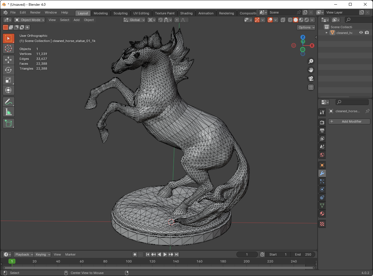
horse_statue_01 from Poly Haven
meshopt_Meshlet
Here’s what meshopt_Meshlet looks like:
struct meshopt_Meshlet
{
    /* offsets within meshlet_vertices and meshlet_triangles arrays with meshlet data */
    unsigned int vertex_offset;
    unsigned int triangle_offset;

    /* number of vertices and triangles used in the meshlet; data is stored in consecutive
       range defined by offset and count */
    unsigned int vertex_count;
    unsigned int triangle_count;
};
As discussed in the previous section, this is just a different way of handling arrays so it’s more GPU access friendly.
Meshlet Build Breakdown
Let’s take a closer look at what’s happening in the meshlet build process. Before we call any of the meshopt functions we need to store some data for later use. In this case it’s just the vertex positions but later we’ll need more:
// Vertex positions
positions = mesh.GetPositions();
After that, we specify our maximum number of vertices and triangles we want the meshet to have:
const size_t kMaxVertices  = 64;
const size_t kMaxTriangles = 124;
const float  kConeWeight   = 0.0f;
Now we call the first of the meshlet building functions meshopt_buildMeshletsBound. This function returns the maximum number of meshlets that’s possible based on the number of indices our mesh has and the maximum number of vertices and triangles.
const size_t maxMeshlets = meshopt_buildMeshletsBound(mesh.GetNumIndices(), kMaxVertices, kMaxTriangles);
Storage is then allocated for the worse case scenario (aka if we hit all the maximum values):
meshlets.resize(maxMeshlets);
meshletVertices.resize(maxMeshlets * kMaxVertices);
meshletTriangles.resize(maxMeshlets * kMaxTriangles * 3);
The meshlets are then built by calling meshopt_buildMeshlets. In addition to writing the meshlet related data to the output, this function also returns the actual number of meshlets that are built.
size_t meshletCount = meshopt_buildMeshlets(
    meshlets.data(),                                               // Output: array of meshopt_Meshlet
    meshletVertices.data(),                                        // Output: array of uint32_t - meshlet to mesh index mappings
    meshletTriangles.data(),                                       // Output: array of uint8_t - triangle indices
    reinterpret_cast<const uint32_t*>(mesh.GetTriangles().data()), // Input: pointer mesh vertex indices
    mesh.GetNumIndices(),                                          // Input: number of vertex indices
    reinterpret_cast<const float*>(mesh.GetPositions().data()),    // Input: pointer to vertex positions
    mesh.GetNumVertices(),                                         // Input: number of vertex positions
    sizeof(glm::vec3),                                             // Input: stride of vertex position elements
    kMaxVertices,                                                  // Input: maximum number of vertices per meshlet
    kMaxTriangles,                                                 // Input: maximum number of triangles per meshlet
    kConeWeight);                                                  // Input: cone weight (we'll discuss this eventually...maybe)
Finally, resize (or trim) the storage to fit the actual number of meshlets built.
auto& last = meshlets[meshletCount - 1];
meshletVertices.resize(last.vertex_offset + last.vertex_count);
meshletTriangles.resize(last.triangle_offset + ((last.triangle_count * 3 + 3) & ~3));
meshlets.resize(meshletCount);
The resize for meshletVertices and meshlets should be pretty obvious. But the resize for meshletTriangles may look confusing if you can’t immediately parse that expression in your head.
Let’s take a look at an example to better understand it.
// Suppose the following
last.triangle_offset = 64; // meshopt always aligns this to 4 bytes
last.triangle_count = 6;

// Calculate the most inner expression:
x = (last.triangle_count * 3 + 3);
x = (6 * 3 + 3);
x = 18 + 3;
x = 21

// Apply the &~3
y = x & ~3;
y = 21 & ~3;
// Change from decimal to binary
y = 10101 & ~11;
// Apply bitwise complement
y = 10101 & 1100;
y = 10100;
// Back to decimal
y = 20;

// Adding the offset
z = last.triangle_offset + 20;
z = 64 + 20;
z = 84; // Aligns to 4 bytes
The math for the resizing of meshletTriangles ensures that its size is aligned to 4 bytes to be GPU friendly. We don’t have to worry about meshletVertices and meshlets since they are naturally 4 bytes aligned based on their element type.
Repacking
Before we send our meshlet data to the GPU, there’s one more thing we need to do. In the meshlet build code above, meshopt_buildMeshlets writes the triangles out to meshletTriangles which is of type std::vector<uint8_t>. This means that the triangles are stored in 3 consecutive bytes (uint8_t). We know this because of how meshletTriangle gets resized initially (and from using it in the samples):
meshletTriangles.resize(maxMeshlets * kMaxTriangles * 3);
While this saves on storage, it might make reading it in the shader a bit complicated. To keep things simple, we’re just going to repack the 3 consecutive bytes into a uint32_t and readjust the triangle offset for each meshlet. This is pretty straightfoward to do.
// Repack triangles from 3 consecutive bytes to 4-byte uint32_t to
// make it easier to unpack on the GPU.
//
std::vector<uint32_t> meshletTrianglesU32;
for (auto& m : meshlets) {
    // Save triangle offset for current meshlet
    uint32_t triangleOffset = static_cast<uint32_t>(meshletTrianglesU32.size());

    // Repack to uint32_t
    for (uint32_t i = 0; i < m.triangle_count; ++i) {
        uint32_t i0 = 3 * i + 0 + m.triangle_offset;
        uint32_t i1 = 3 * i + 1 + m.triangle_offset;
        uint32_t i2 = 3 * i + 2 + m.triangle_offset;

        uint8_t  vIdx0  = meshletTriangles[i0];
        uint8_t  vIdx1  = meshletTriangles[i1];
        uint8_t  vIdx2  = meshletTriangles[i2];
        uint32_t packed = ((static_cast<uint32_t>(vIdx0) & 0xFF) << 0) |
                          ((static_cast<uint32_t>(vIdx1) & 0xFF) << 8) |
                          ((static_cast<uint32_t>(vIdx2) & 0xFF) << 16);
        meshletTrianglesU32.push_back(packed);
    }

    // Update triangle offset for current meshlet
    m.triangle_offset = triangleOffset;
}
Some Numbers
Now that we’ve covered loading a mesh from an OBJ file and creating meshlets from it. Let’s take a look at some numbers.
Stats for horse_statue_01_1k.obj:
- 11239 vertices
- 27310 triangles
- 241 meshlets generated
- 96 triangles and 64 vertices for each meshlet, except the last one which has 65 triangles and 54 vertices
Not too shabby. We’re a bit lower than the max triangle count, but that’s okay.
Creating Buffers From meshopt Output
After we get the meshlet output from meshopt, we need to create buffer objects that we’ll use later to render. The sample code for this part uses some light wrapper functions for each API to make creating buffers with source data less verbose. It’s pretty easy to track down these functions in the GREX project - they’re in the renderer C++ source file for each API: D3D12, Metal, Vulkan. I don’t want to create a hard link to them here since that will force a link to a specific commit and obfuscate any future changes in the code.
My apologies for these confusing names. I’ll try to revise this post and the code later with better names.
postionBuffer - vertex position of the mesh we loaded.
meshletBuffer - meshlets generated from meshopt_buildMeshletsBound.
meshletVerticesBuffer - meshlet vertices generated from meshopt_buildMeshletsBound.
meshletTrianglesBuffer - repacked meshlet triangles.
// D3D12
ComPtr<ID3D12Resource> positionBuffer;
ComPtr<ID3D12Resource> meshletBuffer;
ComPtr<ID3D12Resource> meshletVerticesBuffer;
ComPtr<ID3D12Resource> meshletTrianglesBuffer;

CreateBuffer(renderer.get(), SizeInBytes(positions), DataPtr(positions), D3D12_HEAP_TYPE_UPLOAD, &positionBuffer);
CreateBuffer(renderer.get(), SizeInBytes(meshlets), DataPtr(meshlets), D3D12_HEAP_TYPE_UPLOAD, &meshletBuffer);
CreateBuffer(renderer.get(), SizeInBytes(meshletVertices), DataPtr(meshletVertices), D3D12_HEAP_TYPE_UPLOAD, &meshletVerticesBuffer);
CreateBuffer(renderer.get(), SizeInBytes(meshletTrianglesU32), DataPtr(meshletTrianglesU32), D3D12_HEAP_TYPE_UPLOAD, &meshletTrianglesBuffer);

// Metal
MetalBuffer positionBuffer;
MetalBuffer meshletBuffer;
MetalBuffer meshletVerticesBuffer;
MetalBuffer meshletTrianglesBuffer;

CreateBuffer(renderer.get(), SizeInBytes(positions), DataPtr(positions), &positionBuffer);
CreateBuffer(renderer.get(), SizeInBytes(meshlets), DataPtr(meshlets), &meshletBuffer);
CreateBuffer(renderer.get(), SizeInBytes(meshletVertices), DataPtr(meshletVertices), &meshletVerticesBuffer);
CreateBuffer(renderer.get(), SizeInBytes(meshletTrianglesU32), DataPtr(meshletTrianglesU32), &meshletTrianglesBuffer);

// Vulkan
VulkanBuffer positionBuffer;
VulkanBuffer meshletBuffer;
VulkanBuffer meshletVerticesBuffer;
VulkanBuffer meshletTrianglesBuffer;

VkBufferUsageFlags usageFlags = VK_BUFFER_USAGE_STORAGE_BUFFER_BIT;
CreateBuffer(renderer.get(), SizeInBytes(positions), DataPtr(positions), usageFlags, 0, &positionBuffer);
CreateBuffer(renderer.get(), SizeInBytes(meshlets), DataPtr(meshlets), usageFlags, 0, &meshletBuffer);
CreateBuffer(renderer.get(), SizeInBytes(meshletVertices), DataPtr(meshletVertices), usageFlags, 0, &meshletVerticesBuffer);
CreateBuffer(renderer.get(), SizeInBytes(meshletTrianglesU32), DataPtr(meshletTrianglesU32), usageFlags, 0, &meshletTrianglesBuffer);
API Notes About Buffers and Structs
For D3D12, all the above buffers will be StructuredBuffers and the shader expects them as SRVs that look like this:
StructuredBuffer<Vertex>  Vertices        : register(t1); // positionBuffer
StructuredBuffer<Meshlet> Meshlets        : register(t2); // meshletBuffer
StructuredBuffer<uint>    VertexIndices   : register(t3); // meshletVerticesBuffer
StructuredBuffer<uint>    TriangleIndices : register(t4); // meshletTrianglesBuffer
For Vulkan, the buffers will have the usage flag VK_BUFFER_USAGE_STORAGE_BUFFER_BIT and the shader will also expect them as SRVs that’s identical to D3D12.
For Metal, these are just buffer objects allocated on the device and the shader expects them in the device address space:
device const Vertex*       Vertices              [[buffer(1)]],
device const Meshlet*      Meshlets              [[buffer(2)]],
device const uint*         MeshletVertexIndices  [[buffer(3)]],
device const uint*         MeshletTriangeIndices [[buffer(4)]],
The Vertex struct is syntactically different between the HLSL and MSL code:
// HLSL
struct Vertex {
    float3 Position;
};

// Metal
struct Vertex {
    packed_float3 Position;
};
D3D12 and Vulkan will interpret the Position as 12 bytes and tightly packed. Metal, on the other hand, requires the type to be packed_float3 to interpret Position as 12 bytes wide and tightly packed. If float3 is used in the Metal shader code, Position is interpreted as 12 bytes but packed to 16-byte alignment. Which would break the consistency across the APIs for us.
The Meshlet struct is the same for both HLSL and MSL:
struct Meshlet {
	uint VertexOffset;
	uint TriangleOffset;
	uint VertexCount;
	uint TriangleCount;
};
Rendering Meshlets
Dispatching from the API side
The pattern for the dispatch API call is pretty much the same for all three APIs:
- Set the graphics pipeline [state] object(s) and root signature/pipeline layout
- Set the constant data via the API call (constant data is just an MVP matrix)
- Set the descriptors for the 4 buffers we need
- Call the dispatch function with the meshlet count as the value for threadGroupCountX
PerspCamera camera = PerspCamera(60.0f, window->GetAspectRatio());
camera.LookAt(vec3(0, 0.105f, 0.40f), vec3(0, 0.105f, 0));

mat4 R = glm::rotate(static_cast<float>(glfwGetTime()), glm::vec3(0, 1, 0));
mat4 MVP = camera.GetViewProjectionMatrix() * R;

// -----------------------------------------------------------------------------
// Direct3D
// -----------------------------------------------------------------------------
commandList->SetGraphicsRootSignature(rootSig.Get());
commandList->SetPipelineState(pipelineState.Get());

commandList->SetGraphicsRoot32BitConstants(0, 16, &MVP, 0);
commandList->SetGraphicsRootShaderResourceView(1, positionBuffer->GetGPUVirtualAddress());
commandList->SetGraphicsRootShaderResourceView(2, meshletBuffer->GetGPUVirtualAddress());
commandList->SetGraphicsRootShaderResourceView(3, meshletVerticesBuffer->GetGPUVirtualAddress());
commandList->SetGraphicsRootShaderResourceView(4, meshletTrianglesBuffer->GetGPUVirtualAddress());

commandList->DispatchMesh(static_cast<UINT>(meshlets.size()), 1, 1);

// -----------------------------------------------------------------------------
// Metal - also specifies the number of threads for each threadgroup (128)
// -----------------------------------------------------------------------------
pRenderEncoder->setRenderPipelineState(renderPipelineState.State.get());
pRenderEncoder->setDepthStencilState(depthStencilState.State.get());

pRenderEncoder->setMeshBytes(&MVP, sizeof(glm::mat4), 0);
pRenderEncoder->setMeshBuffer(positionBuffer.Buffer.get(), 0, 1);
pRenderEncoder->setMeshBuffer(meshletBuffer.Buffer.get(), 0, 2);
pRenderEncoder->setMeshBuffer(meshletVerticesBuffer.Buffer.get(), 0, 3);
pRenderEncoder->setMeshBuffer(meshletTrianglesBuffer.Buffer.get(), 0, 4);

// No object function, so all zeros for threadsPerObjectThreadgroup
pRenderEncoder->drawMeshThreadgroups(MTL::Size(static_cast<uint32_t>(meshlets.size()), 1, 1), MTL::Size(0, 0, 0), MTL::Size(128, 1, 1));

// -----------------------------------------------------------------------------
// Vulkan (uses PushGraphicsDescriptor convenience function - found in vk_renderer.cpp
// -----------------------------------------------------------------------------
vkCmdBindPipeline(cmdBuf, VK_PIPELINE_BIND_POINT_GRAPHICS, pipeline);

vkCmdPushConstants(cmdBuf, pipelineLayout, VK_SHADER_STAGE_MESH_BIT_EXT, 0, sizeof(mat4), &MVP);
PushGraphicsDescriptor(cmdBuf, pipelineLayout, 0, 1, VK_DESCRIPTOR_TYPE_STORAGE_BUFFER, &positionBuffer);
PushGraphicsDescriptor(cmdBuf, pipelineLayout, 0, 2, VK_DESCRIPTOR_TYPE_STORAGE_BUFFER, &meshletBuffer);
PushGraphicsDescriptor(cmdBuf, pipelineLayout, 0, 3, VK_DESCRIPTOR_TYPE_STORAGE_BUFFER, &meshletVerticesBuffer);
PushGraphicsDescriptor(cmdBuf, pipelineLayout, 0, 4, VK_DESCRIPTOR_TYPE_STORAGE_BUFFER, &meshletTrianglesBuffer);

vkCmdDrawMeshTasksEXT(cmdBuf, static_cast<uint32_t>(meshlets.size()), 1, 1);
What Happens With the Dispatch Call?
If you’re familiar with GPU compute dispatches, you can skip this part. If you’re not, hopefully this will help you get a better idea of how this all works.
At the time of this writing, the horse statue model that’s used in the sample code generated 241 meshlets. This means that our dispatch calls look like this:
// Direct3D
commandList->DispatchMesh(241, 1, 1);

// Metal - also specifies the number of threads for each workgroup (128)
pRenderEncoder->drawMeshThreadgroups(MTL::Size(241, 1, 1), MTL::Size(0, 0, 0), MTL::Size(128, 1, 1));

// Vulkan
vkCmdDrawMeshTasksEXT(cmdBuf, 241, 1, 1);
This tells the GPU to create 241 workgroups (aka threadgroups). One for each meshlet.
Mesh and Pixel/Fragment Shaders
Finally, let’s take a look at a mesh shader that does some actual vertex processing.
Our mesh shader below does the following in each thread of execution:
- Reads in a meshlet
- Sets the vertex and primitive output count
- Processes and writes the triangle
- Processes and writes the vertex
Why is the number of threads (aka workgroup/threadgroup size) set to 128?
Remember when we generated our meshlets above and we used kMaxTriangles = 124? Well, the 128 threads sufficiently cover the maximum number of triangles that we specified.
128 threads also line up nicely with many of the GPU’s natural warp/wave sizes which are 32, 64, or sometimes 128.
What the heck is gid, gtid, etc?
gid stands for group id - this is an index into the workgroups that we launched from the API dispatch calls. Using the 241 workgroups example above, each workgroup will have a gid assigned to it ranging from 0 to 240. In the mesh shader that we’ll look at soon, the gid is used by the shader to know which meshlet it’s looking at.
Conceptually, it looks something like this:
void Dispatch(int workGroupCount) {
    for (int gid = 0; gid < kWorkGroupCount; ++gid) {
        LaunchWorkGroup(gid);
    }
}

Dispatch(241);
On the GPU, the execution would happen in parallel and not serially as conveyed by the for loop.
gtid stand for group thread id - this is an index into the launched threads within the workgroup. Earlier, we said that each workgroup has 128 threads. Each thread has a gtid assigned to it ranging from 0 to 127. In the mesh shader we’ll look at soon, the gtid is used as an offset to read the triangle and vertex data.
Conceptually, it looks something like this:
void LaunchThread(int gid, int gtid) {
    DoMeshShaderStuff(gid, gtid, ...);
}

void LaunchWorkGroup(int gid) {
    const int kNumThreads = 128;
    for (int gtid = 0; gtid < kNumThreads; ++gtid) {
        LaunchThread(gid, gtid);
    }
}
And again, on the GPU, the execution would happen in parallel and not serially as conveyed by the for loop.
More Numbers
If you’ll recall, earlier we said we’re dispatching 241 workgroups/threadgroups. And just right above, we just said there’s 128 threads per workgroup/threadgroup, does this mean 241*128 threads will be launched? Yes, that’s correct: 30,848 threads will be launched. I know this might seem overly simplistic, but I just want to make sure the two connect for anyone who isn’t familiar with GPU compute.
Full Shader Code
Below are the full mesh and pixel/fragment shaders. I borrowed the color generation code from the D3D12 Mesh Shader Samples.
HLSL for Direct3D and Vulkan
#ifdef __spirv__
#define DEFINE_AS_PUSH_CONSTANT [[vk::push_constant]]
#else
#define DEFINE_AS_PUSH_CONSTANT
#endif

struct CameraProperties {
    float4x4 MVP;
};

DEFINE_AS_PUSH_CONSTANT
ConstantBuffer<CameraProperties> Cam : register(b0);

struct Vertex {
    float3 Position;
};

struct Meshlet {
	uint VertexOffset;
	uint TriangleOffset;
	uint VertexCount;
	uint TriangleCount;
};

StructuredBuffer<Vertex>  Vertices        : register(t1);
StructuredBuffer<Meshlet> Meshlets        : register(t2);
StructuredBuffer<uint>    VertexIndices   : register(t3);
StructuredBuffer<uint>    TriangleIndices : register(t4);

struct MeshOutput {
    float4 Position : SV_POSITION;
    float3 Color    : COLOR;
};

[outputtopology("triangle")]
[numthreads(128, 1, 1)]
void msmain(
                 uint       gtid : SV_GroupThreadID,
                 uint       gid  : SV_GroupID,
    out indices  uint3      triangles[128],
    out vertices MeshOutput vertices[64])
{
    Meshlet m = Meshlets[gid];
    SetMeshOutputCounts(m.VertexCount, m.TriangleCount);

    if (gtid < m.TriangleCount) {
        //
        // meshopt stores the triangle offset in bytes since it stores the
        // triangle indices as 3 consecutive bytes.
        //
        // Since we repacked those 3 bytes to a 32-bit uint, our offset is now
        // aligned to 4 and we can easily grab it as a uint without any
        // additional offset math.
        //
        uint packed = TriangleIndices[m.TriangleOffset + gtid];
        uint vIdx0  = (packed >>  0) & 0xFF;
        uint vIdx1  = (packed >>  8) & 0xFF;
        uint vIdx2  = (packed >> 16) & 0xFF;
        triangles[gtid] = uint3(vIdx0, vIdx1, vIdx2);
    }

    if (gtid < m.VertexCount) {
        uint vertexIndex = m.VertexOffset + gtid;
        vertexIndex = VertexIndices[vertexIndex];

        vertices[gtid].Position = mul(Cam.MVP, float4(Vertices[vertexIndex].Position, 1.0));

        float3 color = float3(
            float(gid & 1),
            float(gid & 3) / 4,
            float(gid & 7) / 8);
        vertices[gtid].Color = color;
    }
}

float4 psmain(MeshOutput input) : SV_TARGET
{
    return float4(input.Color, 1);
}
MSL for Metal
#include <metal_stdlib>
using namespace metal;

struct CameraProperties {
    float4x4 MVP;
};

struct Vertex {
    packed_float3 Position;
};

struct Meshlet {
	uint VertexOffset;
	uint TriangleOffset;
	uint VertexCount;
	uint TriangleCount;
};

struct MeshVertex {
	float4 PositionCS [[position]];
	float3 Color;
};

using MeshOutput = metal::mesh<MeshVertex, void, 64, 128, topology::triangle>;

[[mesh]]
void meshMain(
    constant CameraProperties& Cam                   [[buffer(0)]],
    device const Vertex*       Vertices              [[buffer(1)]],
    device const Meshlet*      Meshlets              [[buffer(2)]],
    device const uint*         MeshletVertexIndices  [[buffer(3)]],
    device const uint*         MeshletTriangeIndices [[buffer(4)]],
    uint                       gtid                  [[thread_position_in_threadgroup]],
    uint                       gid                   [[threadgroup_position_in_grid]],
    MeshOutput                 outMesh)
{
    device const Meshlet& m = Meshlets[gid];
    outMesh.set_primitive_count(m.TriangleCount);

    if (gtid < m.TriangleCount) {
        //
        // meshopt stores the triangle offset in bytes since it stores the
        // triangle indices as 3 consecutive bytes.
        //
        // Since we repacked those 3 bytes to a 32-bit uint, our offset is now
        // aligned to 4 and we can easily grab it as a uint without any
        // additional offset math.
        //
        uint packed = MeshletTriangeIndices[m.TriangleOffset + gtid];
        uint vIdx0  = (packed >>  0) & 0xFF;
        uint vIdx1  = (packed >>  8) & 0xFF;
        uint vIdx2  = (packed >> 16) & 0xFF;

        uint triIdx = 3 * gtid;
        outMesh.set_index(triIdx + 0, vIdx0);
        outMesh.set_index(triIdx + 1, vIdx1);
        outMesh.set_index(triIdx + 2, vIdx2);
    }

    if (gtid < m.VertexCount) {
        uint vertexIndex = m.VertexOffset + gtid;
        vertexIndex = MeshletVertexIndices[vertexIndex];

        MeshVertex vtx;
        vtx.PositionCS = Cam.MVP * float4(Vertices[vertexIndex].Position, 1.0);
        vtx.Color = float3(
            float(gid & 1),
            float(gid & 3) / 4,
            float(gid & 7) / 8);

        outMesh.set_vertex(gtid, vtx);
    }
}

struct FSInput
{
    MeshVertex vtx;
};

[[fragment]]
float4 fragmentMain(FSInput input [[stage_in]])
{
	return float4(input.vtx.Color, 1.0);
}
Mesh Shader Breakdown
Let’s break down the mesh shader to see what’s happening. We’ll use the outline from above as a guide:
- Reads in a meshlet
- Sets the vertex and primitive output count
- Processes and writes the triangle
- Processes and writes the vertex
Reads in a meshlet
This is more or less the same in both shading languages.
// HLSL
Meshlet m = Meshlets[gid];

// MSL
device const Meshlet& m = Meshlets[gid];
MSL is a little bit more verbose since it requires an address space to be specified. We’re using device here to indicate that we’re reading from a buffer that was allocated from the device memory pool.
Sets the vertex and primitive output count
This is almost the same in both languages.
// HLSL
SetMeshOutputCounts(m.VertexCount, m.TriangleCount);

// MSL
outMesh.set_primitive_count(m.TriangleCount);
MSL doesn’t require the mesh shader to explicitly state the output vertex count whereas HLSL does.
NOTE: According to the D3D12 Mesh Shader Spec, SetMeshOutputCounts() must be called before any writes to the output arrays occur.
The Metal Shading Language spec makes no mention of where set_primitive_count should be called. The Apple Mesh Shader Example it calls at the the beginning and the Metal by Example mesh shader example calls it at the end.
Metal by Example mesh shader example to calls it on first thread of the workgroup whereas the Apple mesh shader example does not.
// Metal by Example
if (threadIndex == 0) {
    outMesh.set_primitive_count(meshlet.triangleCount);
}

// Apple Mesh Shader Example
// Set the number of primitives for the entire mesh.
output.set_primitive_count(payload.vertexCount);
Processes and writes the triangle
The only difference here is how the output is written.
// HLSL
if (gtid < m.TriangleCount) {
    //
    // meshopt stores the triangle offset in bytes since it stores the
    // triangle indices as 3 consecutive bytes.
    //
    // Since we repacked those 3 bytes to a 32-bit uint, our offset is now
    // aligned to 4 and we can easily grab it as a uint without any
    // additional offset math.
    //
    uint packed = TriangleIndices[m.TriangleOffset + gtid];
    uint vIdx0  = (packed >>  0) & 0xFF;
    uint vIdx1  = (packed >>  8) & 0xFF;
    uint vIdx2  = (packed >> 16) & 0xFF;
    triangles[gtid] = uint3(vIdx0, vIdx1, vIdx2);
}

// MSL
if (gtid < m.TriangleCount) {
    //
    // meshopt stores the triangle offset in bytes since it stores the
    // triangle indices as 3 consecutive bytes.
    //
    // Since we repacked those 3 bytes to a 32-bit uint, our offset is now
    // aligned to 4 and we can easily grab it as a uint without any
    // additional offset math.
    //
    uint packed = MeshletTriangeIndices[m.TriangleOffset + gtid];
    uint vIdx0  = (packed >>  0) & 0xFF;
    uint vIdx1  = (packed >>  8) & 0xFF;
    uint vIdx2  = (packed >> 16) & 0xFF;

    uint triIdx = 3 * gtid;
    outMesh.set_index(triIdx + 0, vIdx0);
    outMesh.set_index(triIdx + 1, vIdx1);
    outMesh.set_index(triIdx + 2, vIdx2);
}
We use the gtid as an offset to know which meshlet triangle we’re looking at. We use this offset to read the packed triangle from our nicely 32-bit aligned packed triangle indices. Then just some shifting and masking to get the 8-bit indices before writing to output.
Processes and writes the vertex
The only real difference here is the multiplication syntax and the output is written.
// MSL
if (gtid < m.VertexCount) {
    uint vertexIndex = m.VertexOffset + gtid;
    vertexIndex = VertexIndices[vertexIndex];

    vertices[gtid].Position = mul(Cam.MVP, float4(Vertices[vertexIndex].Position, 1.0));

    float3 color = float3(
        float(gid & 1),
        float(gid & 3) / 4,
        float(gid & 7) / 8);
    vertices[gtid].Color = color;
}

// MSL
if (gtid < m.VertexCount) {
    uint vertexIndex = m.VertexOffset + gtid;
    vertexIndex = MeshletVertexIndices[vertexIndex];

    MeshVertex vtx;
    vtx.PositionCS = Cam.MVP * float4(Vertices[vertexIndex].Position, 1.0);
    vtx.Color = float3(
        float(gid & 1),
        float(gid & 3) / 4,
        float(gid & 7) / 8);

    outMesh.set_vertex(gtid, vtx);
}
We use the gtid as an offset to know which local meshlet vertex index we’re looking at. Then we use the local meshlet vertex index to look up the meshes vertex index. Once we have this we can read vertex position data. Then the usual vertex transform followed by writing to output.
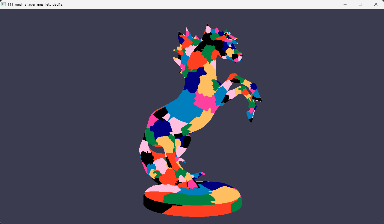
Rendered Image
The 111_mesh_shader_meshlets sample renders this using the mesh shader graphics pipeline line we covered in this post: